For a spreadsheet summary of the parts (but not tools!) you need, see here.
Electronics
- A Raspberry Pi. We used a model A+, and the mounting holes in the weatherproof casing described in the next section are positioned to match the mounting holes on this model. If you move the mounting holes, you should be able to use a model B+. The older models A and B should be fine, too, but you may need to think a bit more about how to mount them securely.
- The Raspberry Pi Camera Module.
- A microSD card, preferrably at least 8GB.
- A microUSB charger appropriate to the Pi, with a long cable. We used this one.
- A WiFi dongle compatible with the Pi, such as the Edimax EW-7811Un. This is optional if you’re using a Model B or B+ and want to connect the Pi to the Internet via an ethernet cable, rather than WiFi.
- A high brightness IR LED such as the IR333A or LD274.
- A 38 kHz IR demodulator. These instructions assume you’re using the TSOP38238.
- A PN2222A transistor.
- Two resistors for the LED circuit. If you’re using one of the diodes listed above, they should be 2700 Ohms and 56 Ohms.
- A ribbon cable compatible with the Raspberry Pi GPIO. If you’re using a model A+ or B+, you need a 40-pin cable; for the model A or B, a 26-pin cable. Sets consisting of an appropriate connector (FC40-P or FC26-P, respectively) plus the cable itself are sold by Adafruit.
Alternately, you can get the two parts separately on Amazon.
- Heat shrink.
Lumber
- 2 ft x 4 ft of 1/4″ thick plywood, preferably smooth (sanded).
- 1/2″ x 36″ square cross-section dewel.
- 3/4″ x 36″ square cross-section dewel.
Hardware
-
Standoffs for mounting the Raspberry Pi within the enclosure. I used,
- Four M2.5 12.0 mm screws,
- Four M2.5 6.0 mm screws,
- Four M2.5 x 10 mm HEX standoffs.
Such small metric standoffs and screws can be difficult to find, but they match the mounting holes on the Pi exactly. I got mine from Mouser.
-
Screws for securing the electronics enclosure. Using screws, rather than glue, to secure one of the sides will let you open it later if you need the Pi for other projects (or have to fix the electronics). Any four sufficiently long screws will do, really, but the drawings assume you’re using,
- Another four M2.5 12.0 mm screws.
- Weatherproofing solution for the plywood, such as Helmsman Spar Urethane.
-
A sealant for the electronics enclosure, such as silicone caulk.
-
Hardware cloth with 1/4″ wire spacing. You only need about 12 by 10 cm, but will probably have to buy a large roll.
-
An IR reflector. We used a smooth but not quite mirror-like piece of aluminium. You can see it in each picture taken by the bird feeder, on the back wall.
-
A macro lens. The minimum focal length of the built-in camera is approximately 47 cm. The bird is typically at a much shorter distance, so without any additional optics the image is very
blurry. A lens extracted from a pair of cheap reading glasses works perfectly fine; we used a +2.75 diopter pair bought for a few dollars at CVS. Without the lens, only objects 50 cm away or further are in focus. With the lens, objects from 20 cm to 35 cm are in focus (as expected from the lensmaker’s equation).You may find this table helpful in choosing a lens.
-
A small hinge for the feeder flap.
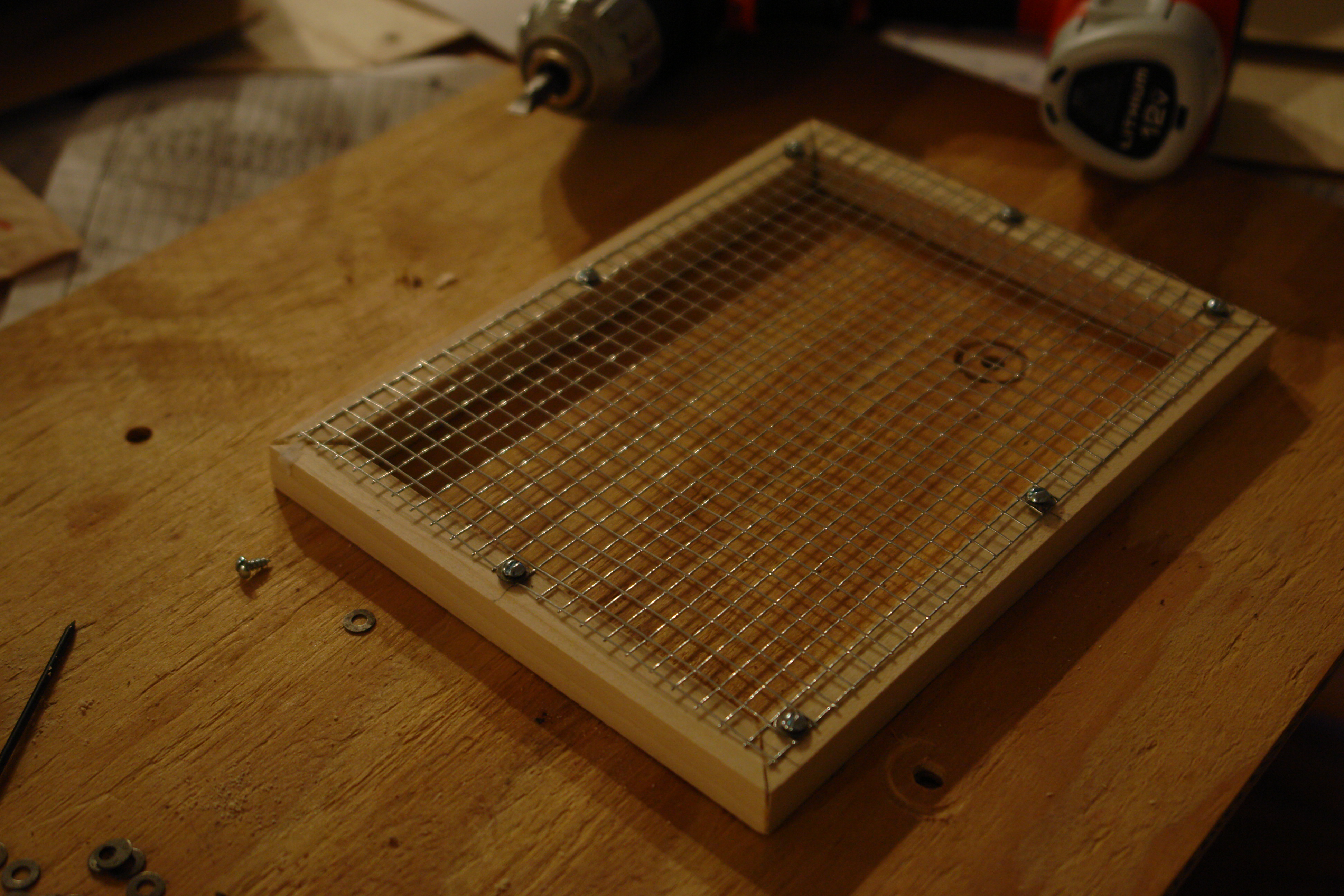
- Some fasteners for attaching the hardware cloth to the frame made of the 1/2″ dewel. If you have access to a staple gun, it will work well. We didn’t, so we used 8 small wood screws (shorter than 1/2″, the thickness of the narrower dewel) with washers.
-
Cable glands for feeding the WiFi and power cables out of the electronics enclosure. These are optional, but will help seal the enclosure against moisture and may save the electronics if the feeder falls off the window. Get sizes compatible with the cables you are using (probably around 5 mm in diameter).
Tools
-
An HDMI cable, monitor and keyboard for setting up the Pi for the first time. (These are not listed in the parts section as you only need them while setting up the device; when you’re done, you can SSH into the Pi instead.)
-
A soldering iron and solder, for assembling the detector circuit.
-
A jigsaw, for cutting out the casing parts from the plywood panel.
-
A power drill with the following drill bits:
- 2.5 mm (or 3/32″)
- 5.0 mm (or 13/64″)
- 7.0 mm (or 9/32″)
- 19 mm (or 3/4″) hole saw
General-purpose bits work fine, but lip-and-spur wood bits will produce cleaner edges.
-
A power sander. Sadly, as it is the design requires sanding some parts of the casing to fit, especially the “longitudinal partition” (this name will be defined in the drawings). We used a small random-orbit sander from Black and Decker.